 I modified a mixer I had made previously. If I was to ever build another one I would use a bigger box and smaller 1/4″ jack sockets. I also might change to an op amp instead of the transistor amp and mayybe add another op amp and a pot to give extra balance between left and right as well as top to bottom.
But the present one works fine and I see no reason for me to build another.
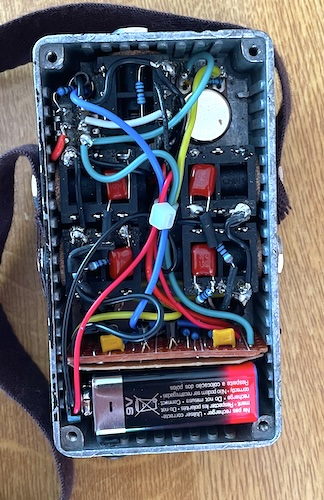
The box is quite packed.
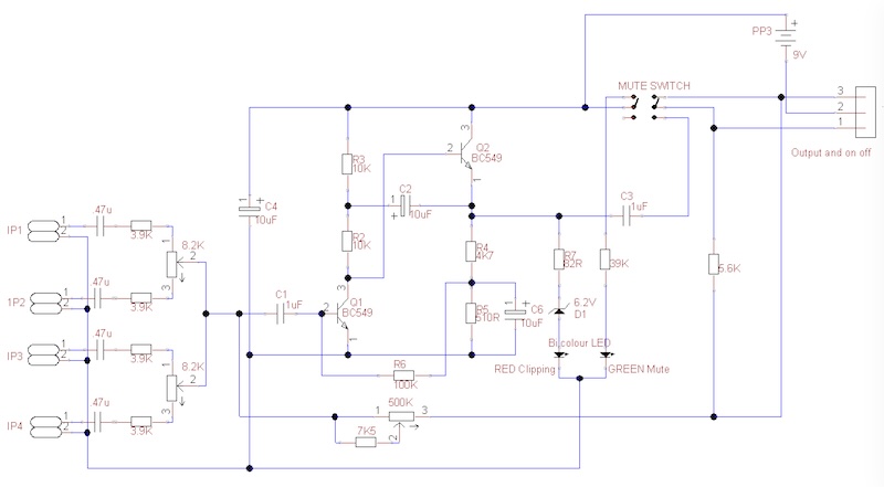
The complete circuit is below. The strange value 8.2K balance pots were bought as 10K!
Testing.
Testing was done using LTspice to simulate the circuit, then verifying with an oscilloscope.
Here is the LTspice simulation schematic
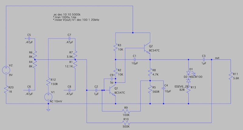
C9 is actually the estimated capacitance between two 5cm long tracks of Veroboard. It actually reduces the HF 3dB point from 190KHz to 50KHz.
Frequency response
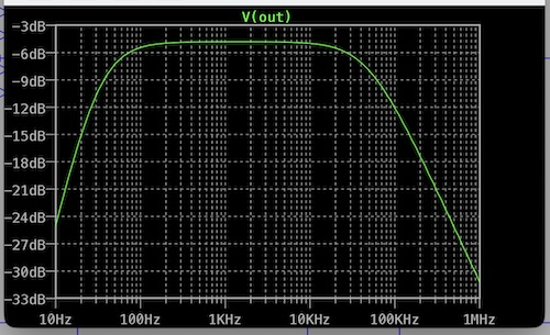
The image shows to frequency response with the balance pot at mid and the gain to the max.
3dB points are 45Hz and 47KHz.
With the oscilloscope I measured 47Hz and 50KHz.
The lower 3db point stays much the same as the gain is reduced but the upper extends to 3MHz at minimum gain. I did not bother to verify this on the scope as it’s and audio amp and above 20KHz is of little interest.
Output level
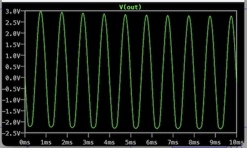
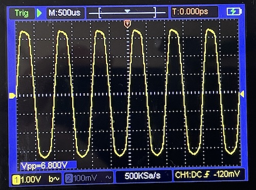
The simulation shows a maximum swing of 5V with clipping on the negative swing.
This is very dependent on biasing, set by the value of R5 and the toe voltage of Q1.
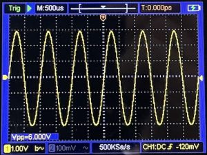
Measurement with the oscilloscope showed a +3V to -3V swing before clipping occured.
‘Scope measurements
Noise
On the Macbook I could reduce the Macbook input level to 10% and increase the signal level using the amp to the right volume for singing with the mic around 12″ away. Noise floor was -75dB. Repeating with and input level of 25% gave a noise floor of -72dB. From a previous article using the input without the amp can give a -65dB noise floor.
The iphone was similar, but without the amp the signal is really too low, and increasing it post recording raises the noise floor to around -45dB.